
Quarter Wave Box Calculator Download
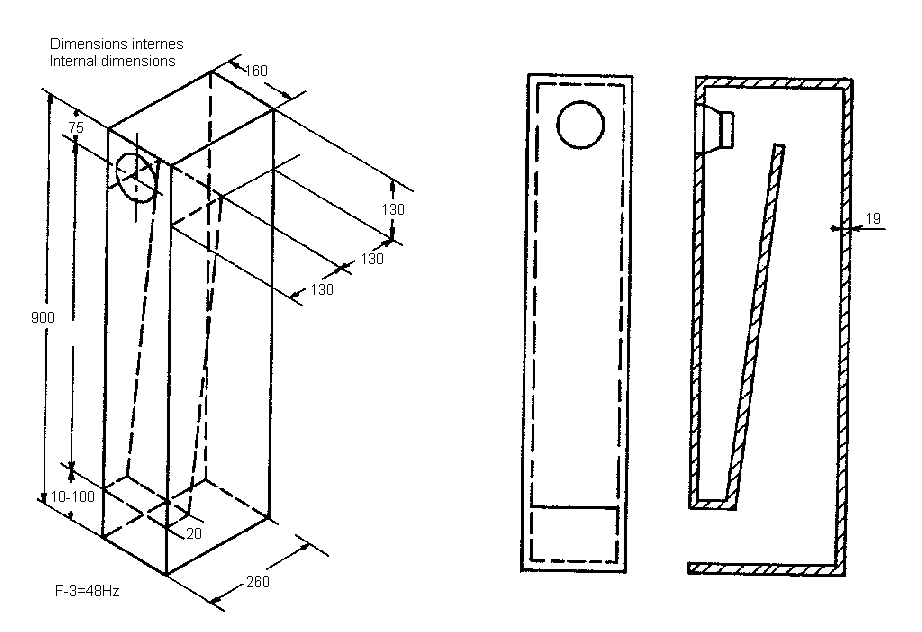
Tapered Quarter-Wave Tube First described by Paul Voigt in 1930, TQWT/QWT uses like a transmission line design pipe lenght of 1/4 wavelenght of driver's resonance frequency. TQWT and QWT stands for (tappered) quarter wave tube and are also refered as Voight Pipes. When constructing a quarter-wave impedance transformer it is important to know the velocity factor of the transmission line to get the lenght of the quarter-wave impedance transformer right. To calculate the quarter wave length of a certain transmission line with a known velocity factor and frequency you may use this calculator.
- Calculate for Box Enclosure Tuning Frequency. F b = Box Enclosure Tuning Frequency A = Air Compliance V = Enclosure Volume or Box F s = Speaker Resonance Frequency.
- Below is a quarter wave ground plane antenna I made for 23cm, 1296MHz which is made from off-cuts of household mains copper wire and a scrap BNC socket from the junk box. The one pictured below is for receiving ADS-B aircraft signals on 1090MHz, again using scrap copper, but this time a purchased N-Type chassis socket.
- Most are under $200 (and usually include an antenna). Next you need an antenna. I prefer one of two antenna's. The first one is an old pirate radio standby called a Comet. Cheap, easy to set up, easy to tune. Model number CFM95SL 5/8 wave. Next, get a cheap laptop. This is your streaming box.
Quarter-wave transmission line speakers employ enclosures that are tuned to provide low-frequency extension for the speaker driver. There are several types of transmission line enclosures and one of the more popular ones is the mass loaded transmission line (MLTL). Basically, an MLTL is a quarter-wave transmission line enclosure with a port.
Outline • • • Quarter-wave transmission line speakers employ enclosures that are tuned to provide low-frequency extension for the speaker driver. There are several types of transmission line enclosures and one of the more popular ones is the mass loaded transmission line (MLTL). Basically, an MLTL is a quarter-wave transmission line enclosure with a port.
Now, some may argue that this is a bass reflex enclosure – and the line is indeed a bit blurry. However, rather than engaging in a lengthy discussion on naming conventions, I will use the term MLTL to describe a ported quarter-wave enclosure.
Thanks to a collection of MathCad programs developed by, Mass Loaded Transmission Line (MLTL) speakers are now relatively straight-forword to design for the DIY audio enthusiast. If you do not have access to MathCad, MathSoft makes a MathCad viewer available, which allows you to work with the programs and perform all the needed simulations. You just cannot save your results. For details, as well as other options for how to obtain MathCad, see. This page is intended as a “Getting Started Guide” for MLTL design.
It is aimed at the DIY speaker designer who is already familiar with MathCad and able to work with Martin J. King’s programs. It is intended as an implementation of design procedure as outlined in the “” thread on DIY Audio and a first draft of a speaker design. Further optimization is likely needed. Driver Selection I happen to have spent quite a while lately drooling over the. I have listened to speakers that used the Alpair 10.3 with metal cones.
Ground Plane Antenna Calculator
I really liked the sound, though, the metallic cones bother me. The provide a boost in the mid treble that I don’t care so much for. The cones are also really fragile. However, the newly available version with paper/fiber cone piqued my interest. The Alpair 10 is classified as a 6″ driver measuring 164 mm in diameter. Much of the diameter is taken up by the surround and mounting flange.
The effective area, Sd, of 88.25 cm² converts to a diameter of 4.2″. Enclosure Design Procedure For MLTLs, there are three fundamental choices: Tapered with narrow top, straight pipe, or tapered with wide top. MLTL Type Top Area Bottom Area Driver Position Ratio TQWT 1•Sd 4•Sd 0.40~0.50 Straight 4•Sd 4•Sd 0.25 Conventional 4•Sd 1•Sd 0.20 Source:. With the MathCad programs it is trivial to try the different types of enclosures. For each taper, work through the design procedure and pick the configuration that provides the smoothest frequency response.
According to Bob Brines, drivers with Qts. Sygic gps maps for windows ce emulator download.